Mathematical Definition
HybridSystem defines a hybrid dynamical system that has both continuous and discrete dynamics, such as bipedal locomotion. This class provides basic elements and functionalities of a hybrid dynamicsl system. The mathematical definition of the hybrid system is given as
\[\mathscr{HC} = \{\Gamma, \mathcal{D}, U, S, \Delta, FG\}\]where,
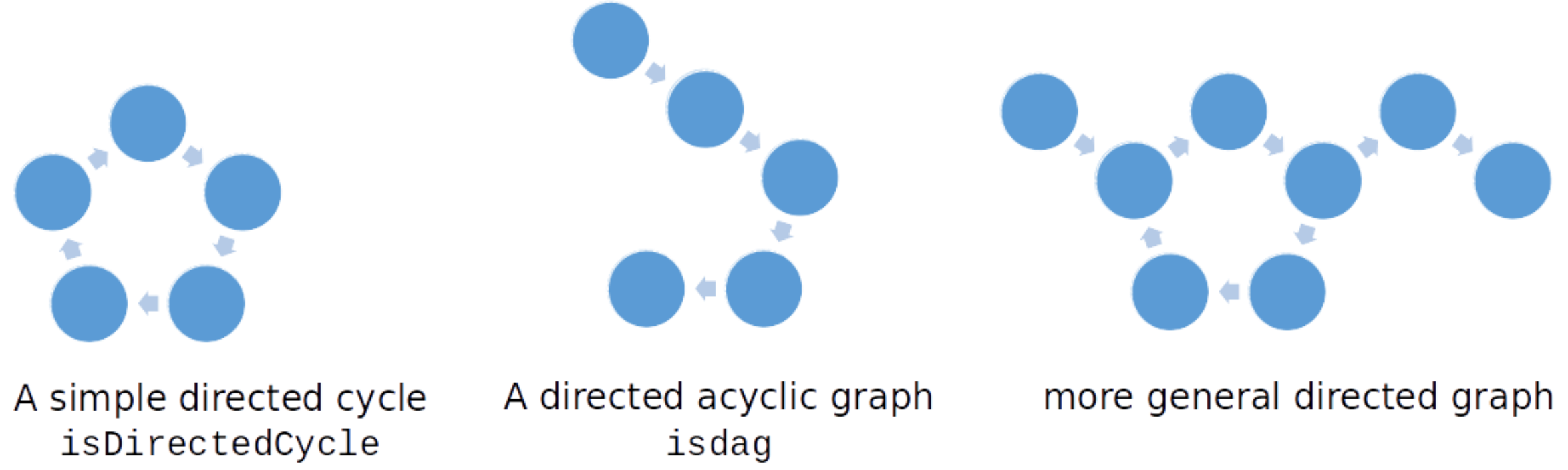
- $\Gamma={V,E}$ is a
directed graphwith a set of vertices $V={v_1, v_2, \dots}$ and a set of edges $E={e_1 = {v_1 \to v_2},\dots}$; - $\mathcal{D}$ is a set of admissible
domainsrepresents the continuous dynamics of the system; - $U$ is a set of admissble controllers on each domain;
- $S$ is a set of
switching surfacesorguardsrepresents the conditions for discrete transitions; - $\Delta$ is a set of
reset mapsof the discrete transitions; - $FG$ is a set of
continuous dynamicson the domain.
Overview
FROST uses HybridSystem class to represent a hybrid dynamical system model. The implementation is heavily based on the Matlab’s digraph data type, with wrapper functions with additional validation.
A directed graph consists of two elements:
-
Nodes: represent vertices in the hybrid system model. Each node has the following properties associated:
- Domain: a admissible domain configuration object
- Control: a controller object
- Param: the parameters associated with the Control and Domain
-
Edges: represent edges in the hybrid system model. Each edge has the following properties associated:
- Guard: an object of type Guard_, contains the guard condition and options for reset map associated.
- Weight: a default property for MATLAB’s digraph objects.
Construct a hybrid system model
To create a hybrid system object, you start with specifying a model name at construction:
>> sys = HybridSystem('some_model_name');
Once you create a HybridSystem object, you can add vertices/edges to complete the construction.
Add vertex to the graph
There are multiple ways to add a vertex to the directed graph of a hybrid system model:
- The simplest way to use (
prop, value) pairs to specify a vertex:
>> sys = sys.addVertex('some_vertex_name', 'some_prop', some_prop_value, ...);
The available properties for a vertex are Domain, Control, Param. The
(prop, value) pairs are optional when adding a new vertex to the graph. You
can modify the vertex property afterward by calling the function:
>> sys = sys.setVertexProperties('some_vertex_name', 'some_prop', some_prop_value, ```.)
- Use table to specify a single or a group of vertices:
>> sys = sys.addVertex(T);
where T is a table argument which must have a variable named Names. To
specify the vertex properties in the input table, make sure to use the same set
of variable names as the directed graph Nodes table.
- You can also add arbitrary number of vertices by specifing the number of vertices to be added:
>> sys = sys.addVertex(3);
The above command will add 3 empty vertices to the graph named Node1, Node2,
and Node3. The properties of these vertices can be specified afterward using
the function setVertexProperties;
Remove vertex from the graph
You can also remove a single vertex or a group of vertices from the graph using
the rmVertex function:
>> sys = sys.rmVertex('some_vertex_name');
or
>> sys = sys.rmVertex({'some_vertex_name', 'another_vertex_name', 'yet_another_vertex_name'});
The input argument can be a string of the single vertex or a cell array of multiple vertices’ name.
Add edges
There are two ways to add edges to the graph: you can either use a table or by
specifying the source and target domains of the edge.
- The syntax is very similar to add vertex when using a table:
>> sys = sys.addEdge(T);
T must have a variable
named EndNodes, which is a $N \times 2$ array specifying source and target
vertices.- Edges can be also added by running the following code:
>> sys = sys.addEdge(srcs, tars, 'some_prop', some_prop_value, ...);
where srcs is a cell array of the name of source vertices, and tars is a
cell array of the name of target vertices. The properties values are optional
when first add an edge to the graph. You can specify the edge properties by
using the function setEdgeProperties:
>> sys = sys.setEdgeProperties(srcs, tars, 'some_prop', some_prop_value, ```.);
Remove edges
Edges can be simply removed from the graph by running:
>> sys = sys.rmEdge(sys, srcs, tars);
Visualize
One visualize the direct graph structure of the hybrid system by running:
>> plot(sys.Gamma);